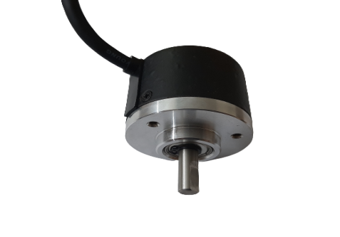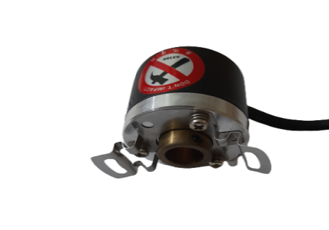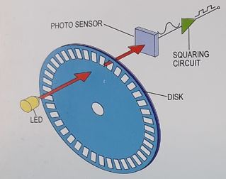
The basic construction of an incremental encoder is shown to the left. A beam of light emitted from an LED. passes through a transparent disk patterned with opaque lines, ands picked up by a photodiode array. The Photodiode array (also called a photo sensor) responds by producing a sinusoidal waveform which is transformed into a square wave, or pulse train. incremental encoders are available in two basic output types, single channel and quadrature. A single channel encoder, often called a tachometer, is normally used in systems that rotate in one direction only, and require simple position and velocity information Quadrature encoders have dual channels (A and 8), phased 90 electrical degrees apart.
These two output signals determine the direction or rotation by detecting the leading or lagging signal in their phase relationship.
Quadrature encoders provide very high speed bi-directional information for very complex motion control applications. incremental encoders can provide a once-per- revolution pulse (often called index, marker, or reference) that occurs at the same mechanical point of encoder shaft revolution. This pulse is on a separate output channel(z) from the signal channel or quadrature outputs. The index pulse is often used to position motion control application to a known mechanical reference. Resolution is a term used to describe the Pulses Per Revolution (PPR) for incremental, encoders or the total number of unique positions per revolution for an absolute encoder. Each incremental encoder has a defined number of cycles that are generated for each full 360 degree revolution. These cycles are Monitored by a counter or motion controller and converted to counts for position or velocity control. Absolute encoders generate a unique code word for every resolvable shaft angle (often called bits or pulse per revolution).

