
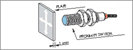
STANDARDIZED SENSING PLATE
The std. plate is square and has a thickness of 1 mm, the material of this plate must be steel (Fe37). Other materials mean that different intervention distances are obtained. The length of the sides of the plate must correspond to the diameter of a circle that is the active surface of the sensor. A larger plate does not result in an increase in the nominal intervention distance, however a reduction in the plate reduces the intervention distance.
APPLICATIONS
Inductive sensors have wide uses in many applications, even in the most difficult working conditions for example in the presence of oils, powders, liquids and vibrations which do not have any effect on their secure functioning.
SARJAN sensors are mounted on machine tools, textile machines,transferline transport systems, packaging equipment, in the automobile industry and in all applications where solutions for automation are required.
ACTIVE FACE
The active face of proximity sensor is the surface from which emits an oscillating field where a metallic object (inductive) or any material (capacitive) results in a change of state of the sensor without entering in contact with it.
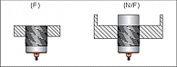
EMBEDDABLE (FLUSH MOUNTING) SENSORS (F)
The metal body covers the sensing area on all sides allows the unit to be installed in metal parts or next to other sensors without causing problems of reciprocal interference.
NOT EMBEDDABLE (NON FLUSH MOUNTING) SENSORS (N/F)
The metal body leaves uncovered part of the sensing area resulting in an increased sensing distance. During installation it is important to remember the minimum distances from metallic parts in the case of inductive units and from any type of material in the case of capacitive units. It is not possible to mount more than one sensor side by side.
NOMINAL INTERVENTION DISTANCE (Sn)
The nominal distance is defined as the switching value where variations due to Changes in temperature and voltage are taken into account.
REDUCTION FACTORS IN INDUCTIVE
If the object to be sensed is not Fe37 (inductives) the intervention distance Further more if the object to be sensed has dimension and thickness less than those indicated then the intervention distance will be further reduced.
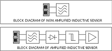
INDUCTIVE SENSORS
Aq 37 1 x S
Stainless steel 0.9 x Sn
Brass-bronze 0.5 x Sn
Aluminum 0.4 x Sn
Copper 0.4 x Sn
SUGGESTIONS FOR MOUNTING
- Follow the indications listed in the technical characteristics for the various Families of sensors.
- Take note of the temperature limits indicated for each family of sensors. Incorrect installation may result in a modification in the switching distance Causing a change in equipment performance.
- When using sensors in areas where chemicals are present it is advised that It may be difficult to establish their corrosiveness. Generally speaking the plastic parts have a high resistance to oil, salts, petrol and other hydrocarbons.
- Do not pull the cable with excessive force and if necessary use protective Tubing.
- Install both inductive and capacitive sensors in such a way as to avoid that Any kind of material becomes deposited on the active surface.
- When installing sensor using locknuts do not overtighten them in order to Avoid damage to the body of the sensor and the internal circuit. Particular Attention should be given to sensors with a diameter equal to or less than 12 mm. Attention should all be given to avoid the installation of a sensor into a Hole with the same diameter as this may cause irreparable damage. is recommended that further information be requested from our technical
SWITCHING DISTANCE (Sn)
- This is the switching distance measured at 20°C and nominal supply voltage, using a square piece of Fe 37 (EN50010) steel of 1 mm. thickness the side of which must be equal to or greater than the diameter of the active surface. In this condition the sensor switches in a Sn range of “10% Sn.
View PDFs
M05 Inductive Proximity Switch Threaded
M05 Inductive Proximity Switch
M06 Inductive Proximity Switch
M08 Inductive Proximity Switch (with 4-pin Male Connector)
M08 Inductive Proximity Switch
M12 Inductive Proximity Switch (with 4-pin Male Connector)
M12 Inductive Proximity Switch
M12 Namur Inductive Proximity Switch
M18 AC Inductive Proximity Switch
M18 Analogue Inductive Proximity Switch
M18 Current Analogue Inductive Proximity Switch
M18 DC 2 wire Inductive Proximity Switch
M18 Inductive Proximity Switch
M18 Inductive Proximity Switch (with 4-pin Male Connector)
10 Flat Inductive Proximity Switch
Block 17 x17 Inductive Proximity Switch
Block 20 X 20 Inductive Proximity Switch
M18 X 30 Inductive Proximity Switch
M30 Inductive Proximity Switch 4-Pin
M30 Inductive Proximity Switch
M36 Inductive Proximity Switch 4-Pin